By Glenn Browning
Reproduced from the January 1928 issue of Popular Radio
FINDAMENTALS in radio design have not changed much in the past few years, contrary to the, belief of the general public, and receivers which ere originally based upon sound electrical principles have remained practically unchanged. The original Browning-Drake circuit of 1924 has had very few changes made in its essential principles. However, it has been found advisable, from time to time, to change the mechanical design so that the receiver might be brought up to date in appearance and also to incorporate electrical improvements which have developed in the last few years.
Advertisement for the 1928 Browning-Drake receiver kit, now with single-dial tuning.
Due to the fact that many fans are desirous of using power amplifiers which incorporate either 171 type valves in push-pull arrangement or 210 type valves, in order to get a large mount of undistorted energy delivered o the reproducer, it is thought advisable to describe in this article a two-valve Browning-Drake tuner combined with the new AmerTran power-pack amplifier. This makes a fine combination, inasmuch as a tremendous undistorted volume may be delivered to the reproducer.
The Browning-Drake circuit consists essentially of one stage of tuned-high frequency amplification, with a specially built slot-wound high-frequency transformer which was developed by he writer and Dr. F. H. Drake. This combined with a regenerative detector, the stage of high-frequency amplification being neutralized. The resulting combi-nation makes a tuner which is both easy to build and sufficiently sensitive to enable the operator to receive almost all signals which are above the noise level.
The antenna circuit incorporated in the Browning-Drake receiver is a conductively coupled one; that is, the antenna lead connects directly to a tap on the antenna coil through a .0001 mfd. condenser. This system has proven extremely efficient, inasmuch as it has a much more even response over the entire broadcast band of frequencies than any other simple circuit tested by the author. Another advantage is that good signal strength may be secured when using even an extremely short antenna. One disadvantage, however, is that it is extremely difficult to make the two condensers on the receiver run together when both long and short antennas are being used alternately. Dr. Drake and the writer have, for the past season, been working on what might be termed a "single control" for this circuit and have so designed the receiver that; the tuning condensers employed may be attached to one shaft and controlled with a drum-type illuminated dial without making any other adjustments for certain types of antennas. The receiver described, however, employs what is termed a "trimmer condenser" in parallel with the first tuning condenser. The operator will find that, in most cases, it will be necessary to make slight adjustments on this for different stations.
The RF circuit of the Browning-Drake receiver. Basically unchanged from the original circuit, this one now used type 27 tubes. Note the unuslay way they show the cathodes of these tubes.
Another change which has been made is that a neutralization system has been developed in order that a large valve may be used as the high-frequency amplifier. The neutrali-zation system, as will be noted from the schematic wiring diagram in Figure 1, consists of a number of extra turns added on the secondary of the high-frequency transformer, with the end connected to the rotor plates of the neutralizing condenser, the stator plates then being connected to the grid of the first vacuum valve.
It has also been found advisable, even with this system of neutralization, to keep all high-frequency currents out of the "B" supply. Consequently a condenser of .5 mfd. capacity is placed in the line which runs to the primary of the high-frequency transformer, and a parallel feed is employed which incorporates a high-frequency choke connected directly to the plate circuit of the vacuum valve, the other end going to, a variable resistance and then to the "B" supply.
Perhaps some of the readers may wonder why a .5 mfd. condenser was used in this parallel feed system, inasmuch as it would seem that high-frequency currents could readily pass through as small a condenser as a .006 mfd. It is true that the high-frequency currents can pass through a .006 condenser, but the .006 has a large impedance to all low-frequency currents, and it is known that if a plate impedance is added in a high-frequency amplifier valve detection of signals occurs in this valve and it does not act solely as a high-frequency amplifier. Therefore, keeping this in mind, various sizes of condensers were experimented with, and it was found that a .5 mfd. condenser was about as small as could be used in the place indicated above without seriously impairing the operation of the first vacuum valve.
Shielding is, for the first time, being recommended for the kit set circuit. The previous official kit set was made as sharp as possible, but when located within a radius of a few miles from broadcasting stations it was found that such a large amount of signal was picked up on the coils and the wiring of the set that it was extremely difficult to receive distance while the locals were on. When located as much as four or five miles from broadcasting stations, the receiver operated very satisfactorily, however. The set builder may now choose whether to shield the receiver completely or not, and he should govern his choice by his local receiving conditions. If he is located in an extremely congested section, he should, by all means, completely shield the two-valve tuner; on the other hand, if he is located in the country, this would be an added expense and is unnecessary. In order to facilitate the use of shields and not make the tuner too cumbersome, it was found necessary to cut the tuning coils down from the- 3-inch form to a 2-inch form. The shielding, in all cases, must be kept a distance of 1 inch away from the low potential end and a distance 1-1/2 inches away from the high potential end of the coils, in order that their efficiency be not reduced.
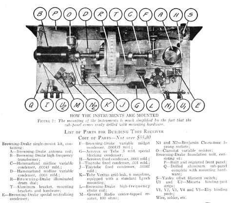
The kit for the new Browning-Drake might be termed a "single-mount unit," as the instruments it employs—two Browning-Drake condensers, driven by the single illuminated drum dial, together with the two coils necessary for the circuit-are all mounted to make a single unit. In fact, it is only necessary to secure the foundation unit, which consists of front and base panel and mounting hardware, to make a tuner which may be used with any type of low-frequency amplifier. Furthermore, it may be constructed for operation with either AC or DC vacuum valves.
How to Assemble the Receiver
Although the two-valve tuner is quite easy to assemble, with the aid of the accompanying work sheet and diagrams, a few constructional tips might be given to advantage. There are two long leads in the set which carry high-frequency currents; one runs from the .5 mId, condenser in the plate circuit of the high-frequency valve to the primary of the high-frequency transformer, and the other runs from the end of the high-frequency transformer to the rotor plates of the neutralizing condenser. These two connections should be kept away from all other leads. Other high-frequency connections, such as that from the stator plates of the condenser to the grid of the vacuum valve, should be run as directly as possible.
In order that the set builder may use shielding if his location is such as to demand it, a metal sub-panel is employed. The grid-leak on the detector valve is suspended by a stiff wire from the stator plates of the second tuning condenser directly to the grid connection on the valve.
Using AC Valves in the Set
If the set builder desires to use the new type, AC valves, he should provide himself with two five-prong sockets, as well as one center-tapped resistor of about 30 to 100 ohms. He should also secure two 227 type AC valves. These are heater type valves and require a step-down transformer which supplies 2-1/2 volts to heat their filaments. The filament connections should be made by means of two wires twisted together. This is extremely necessary if there is to be no AC hum in the completed receiver. All the twisted pairs also should be run underneath the sub-panel.
The high-frequency valve should have from 3 to 4-1/2 volts of negative "C" battery bias. No binding posts are put on the sub-panel for this connection, as it is best to run them out in a cable, preferably using two different colored wires twisted together.
The set builder will find that if he is extremely careful in constructing the receiver for use with these valves he will get no hum whatsoever. It is sometimes necessary, instead of connecting the cathode directly to the center point of the filament circuit, to put in a 22 or 45-volt bias, as recommended in the instructions which accompany the valves. The writer, however, found that in the majority of cases this was not necessary and that the cathode can be connected directly to the center tap of the resistor which is connected across the filaments. A little experimenting on this point is well worth while.
Balancing the Set With AC Valves
In case the set builder chooses to use AC valves with the two-valve Browning-Drake kit set, the balancing or neutralizing of the set should be done as follows: The Clarostat, which is used as a volume control, should be turned clockwise as far as it will easily go. Set the condensers at a low value, say 20 on the scale. Turn the tickler coil down until the second circuit is oscillating. This may be determined by touching the finger to the stator plates of the second tuning condenser (the one to the right as one faces the set). The tickler coil should then be set back so that this circuit just goes out of oscillation. Adjusting the trimmer condenser will, if the set is not neutralized, throw this circuit into oscillation, which may be determined as mentioned above. Set the neutralizing condenser so that turning the trimmer condenser has no affect on the oscillation produced in the second circuit. The set is then completely neutralized.