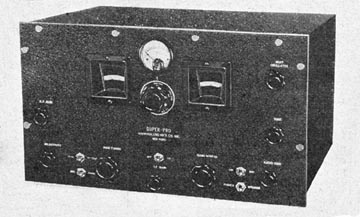
In an earlier article about your editor's experience with the Alaska Communications System (part of the Army Signal Corp) I noted that the main receivers used were Hammarlund Super-Pros. We had other brands as well but the Super-Pros were the most stable and dependable.
We had a Hallicrafters Super Skyrider which we never used except for entertainment. It just wouldn't stay tuned for any length of time. Perhaps a National HRO would have been good but because it didn't have a directly-calibrated dial it wasn't easy to find a particular frequency, especially for some of relatively unskilled people at the receiver station.
These receivers were in operation twenty-four hours a day, day in and day out. They were used mostly for teletype reception using a frequency shift system of a few kc which required fairly accurate tuning and the ability to stay tuned for long periods. It was necessary to change frequencies during the day as atmospheric conditions varied; generally some high frequency during the day and lower ones at night. Tuning was routinely checked every hour of so to make certain all was okay.
The Super-Pro was introduced in 1935 in two basic models, one with, and one without, a crystal filter. It had sixteen tubes on two chassis. The power supply was separate from the main chassis.
The tubes used were 6D6's in the R.F. and I.F. stages, a 6A7 mixer, 6C6's for the local and beat oscillators, two 6B7's as fourth i.f. and detector, and AVC amplifier and rectifier. The audio used a 76 driving a triode-con-nected 42 which in turn drove two triode-con-nected 42's in the output. The power supply chassis had a 5Z3 and a 1V. The 1V was used for grid bias on the various sections of the radio (but surprisingly, not for the output stage).
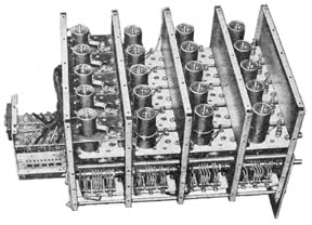
The tuner section of the Hammarlund Super-Pro<
The tuner section of the Super-Pro takes up about a third of the chassis and is unique. Band-switching is accomplished by knife-like switch of five sections which are operated by a series of cams on the band-switch shaft. Each section consists of a double-pole, five-position set of contacts which are silver-plated. The band-switching shaft has no stop so that it can be turned in any direction to change bands. Controlled by this switch are twenty coils in four separate shielded compartments of five coils each, thus the four coils for any given range are individually shielded from each other
The five antenna coils have electrostatic shields (screens) be-tween their primaries and secondaries to avoid capacity coupling between the two windings. Each coil has an air dielectric tuning capacitor as well as an adjustable core to enable alignment at both ends of each band. Two multi-section tuning capacitors are used, one for general coverage and the other (smaller) one for band-spread tuning on the highest ranges. The five ranges covered by this tuner were 540 to 1,160 kc, 1,160 to 2,500 kc, 2,500 to 5,000 kc, 5000 to 10,000 kc, and 10,000 to 20,000 kc. |
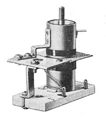 Typical antenna coil showing the static shield between the windings. RF and Oscillator coils were similar except for the shield |
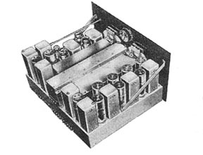
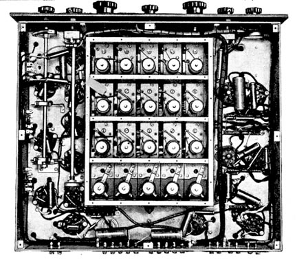 Bottom view of the receiver chassis with the tuner cover removed. |
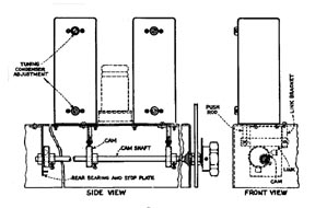 Illustration of the variable-selectivity IF transformers. The cams raised or lowered the bottom winding in relation to the top winding. |
Two of the I.F. stages have transformers whose primaries and secondaries can be varied in relation to each other for a variable bandwidth. The spacing of these windings is controlled by cams on the bandwidth control shaft. The automatic volume control system used an additional amplifier stage (a 6B7 tube) and the AVC voltage was applied to every R.F. and I.F. stage. A switch on the front panel could disable the AVC system for cw (code) reception. Three gain controls were provided on the front panel. These were R.F, I.F. and A.F. (volume). A tone control was included but it was just the simple type which cut the treble response.
This basic design continued until after World War II with a few relatively minor changes. Most notable was the switch to metal tubes (6K7's, 6L7, 6J7's, 6SK7's, 6H6's, 6C5 first audio and 6F6's final audio). Later models added a noise-suppressor circuit which used a 6N7. The separate R.F. and I.F. gain controls were eliminated and replaced with one control which controlled both circuits.
The tuner subassembly was relatively unchanged throughout production. Later versions could be had in three ranges. One of these was as described above. Another was 1,250-2,500, 2,500-5,000, 5,000-10,000, 10,000-20,000 and 20,000-40,000 kc. The third was 100-200, 200-400, 2,500-5,000, 5,000-10,000, and 10,000-20,000 kc.
While designed as a communications re-ceiver, Hammarlund promoted a home version in a console cabinet during the mid-thirties. It probably never became popular, not only because of the cost but also due to the need to change bands in the middle of the standard broadcast band, and the number of controls which would have certainly confused the non-technical user.
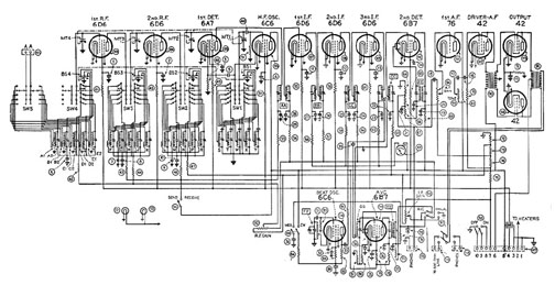
Schematic of the 1935 version of the Super-Pro
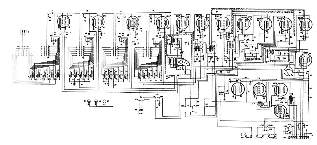
Schematic of the post-war version of the Super-Pro
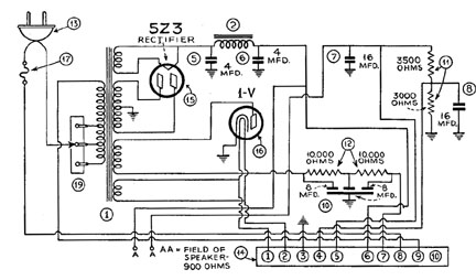
Schematic of the power supply of the Super-Pro