The Retrosonic Receiver
The March 1927 issue of Popular Radio featured an English-made radio of unusual (to say the least) design. The circuit was the product of a Mr. H. W. Roberts, an amateur experimenter in Sheffield, England. It was granted a British patent number 256998. This circuit was claimed to be extremely sensitive and selective, comparing favorably with the superheterodyne.
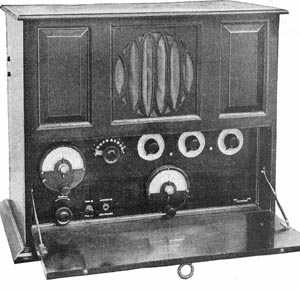
Front View of the Retrosonic
The circuit is interesting in that there is no "B" power supplied to the plate of the second tube. It is also strange that the "B" voltage is almost short-circuited through the windings of the speaker and the primary winding to the low-frequency (audio) transformer, 15. The article notes that the resistance of these two units was quite high and that this apparent "short" was of no consequence.
A look at the schematic certainly puts this circuit on the "weird" category. The Popular Radio article noted that even Mr. Roberts could not explain just how it worked. Following is the explanation given in the magazine.
"Commencing at the antenna it will be seen that the tapped inductance, 5, conveys the incoming impulses directly on to the grid of the first tube through the biasing battery, 8. Considering the first tube as a high-frequency amplifier only, amplified high-frequency currents will flow through the tickler coil, 12, which is in the plate circuit of the tube.
"At the same time a part of the antenna energy, reinforced by regeneration from the tickler coil, 12, will find its way from the grid coil, 5, to the tuned loop circuit, 9 and 10, via the single direct lead, YY, and the loop circuit will thus be impulsed as well.
"In other words, the single point connection through the lead, YY, from the grid of the first tube to the loop circuit, 9 and 10, conveys voltage impulses which build up, by resonance effect, into an oscillatory current of considerable magnitude inside the loop circuit, provided the latter is exactly tuned to the frequency of the incoming signal.
"Thus, large voltages will accordingly be induced across the coil, 9, which are than applied across the grid and plate of the middle tube. Correspondingly amplified currents my therefore be expected to flow in the plate circuit of that tube. It will be noticed that the grid of the second tube is also biased. This is done to neutralize any possible tendency for a positive potential to be impressed on the grid by virtue of the biasing battery of the first tube, for there is a circuit between the positive terminal of the first grid-bias battery and the grid of the second tube.
"Coupled to the coil, 9, is another coil, 11, which is in the plate circuit of the third tube. A form of high-frequency coupling results, so that impulses circulating around the tuned loop circuit induce similar currents in the coil, 11. These currents, flowing through the primary of the low-frequency amplifying transformer, 15, produce similar currents in the secondary winding, which are then impressed upon the grid of the third tube. The plate of this tube, it will be observed, is provided with a high-frequency path through the loudspeaker shunting the condenser, 16, and the tickler coil, 12, back to the plate of the first tube as shown in the diagram.
"For many years it has been known that thermionic tubes, no matter whether used for high-frequency or low-frequency amplify-cation, have a tendency at the same time to rectify or detect signals to a certain extent, and particularly so when they are overloaded. On account of this fact it has been suggested that, in the case of certain multi-tube sets, signals are already half detected before the detector is reached, and the condition, spread over the entire circuit, is known as cumulative rectification.
"There is no detector provided for in the Retrosonic circuit, as the reader may see from the circuit diagram, yet signals are detected or rectified in this receiver.
"Such high-frequency impulses as are applied directly to the first tube are rectified owing to the presence of the grid-bias battery, 8, what is known in England as "anode bend" rectification being the result. In this method of rectification, which does away with the conventional grid condenser and grid leak (which introduce damping and thus cause distortion and lack of selectivity), the grid of the tube is negatively biased so that it operates on the lower bend of its characteristic curve. Positive half cycles then carry the grid potential up the curve, while negative impulses are cut off altogether, thus effecting rectification.
"Partial rectification occurs again at the second tube, where any high-frequency impulses reaching the grid will be rectified for the same reason as in the case of the first tube-because of the grid-bias battery. Finally, a blocking condenser isolates the grid of the last tube, which again tends to cause partial rectification. Signal impulses therefore appear to gradually rectify themselves as they progress through the set.
"That being so, we must revise our description of the progress through the set of received impulses, for the process is now complicated by the introduction of low-frequency currents into circuits which before we only considered as carrying high-frequency currents. Thus, rectified or low-frequency impulses from the output of the first tube will flow through the tickler coil, 12, and because this is coupled to the coil, 5, are partially transferred to the coil, 5, giving rise to a species of low-frequency regeneration between the grid and plate circuits of that tube. Also, some of the low-frequency currents find their way into the tuned loop circuit, 9 and 10, and are thus amplified at those frequencies across the plate and grid of the second tube. Finally, the low-frequency currents flowing through coil 9 are transferred over to the coil, 11, and thus to the grid of the third tube, through the low-frequency transformer, 15. It would appear, therefore, as if some form of reflex action does occur in the Retrosonic circuit, but it is not a reflex circuit of the usual type by any means.
"The inventor of this new circuit attaches the greatest importance to the design and dimensions of the tuned loop circuit, 9 and 10, and its coupling coil, 11. For the reception of broadcast signals lying between 100 and 600 meters he expressly states that the primary coil, 9, must have 64 turns of No. 24 wire and the secondary coil, 11, 89 turns of No. 28 wire, giving an inductance value of 389 microhenries. These coils may be wound as plain solenoids, on formers 3-1/2 inches in diameter, or, for convenience in coupling, may be plug-in coils mounted in a double-coil mounting. The same applies to the arrangement of the antenna inductance and its associated tickler coil. The tuning condenser, 10, in the tuned loop circuit should have a maximum capacity of not more than .0005 mfds.
"It has already been remarked that the plate of the second tube has no "B" power connection. Another function of the hard-worked tuned loop circuit is, apparently, to take care of this anomaly, for the inventor states that although there is no direct high-voltage connection to the plate of the second tube, it is found in practice that a difference of potential will be set up between the plate and grid which is approximately equal to the voltage of the "B" battery. This potential difference can actually be detected (when the set is in operation and receiving signals) by means of a suitable high-resistance voltmeter connected across the plate and grid of the second tube. There is therefore ample evidence of the building up of oscillatory currents of considerable magnitude in the tuned loop circuit.
"To summarize the operation of the receiver in the inventor's own words: "The incoming signals are applied at high frequencies directly to the grid of the first tube, and simultaneously (in part) to the grid of the second tube through the branch lead to the loop circuit, 9 and 10. "From here they are transferred to the grid of the third tube and so back to the coil, 12. "Partial rectification takes place in the first tube owing to the action of the grid battery, 8; and in a similar operation takes place in the second tube owing to the presence of the grid cell, 8. "Finally, any high-frequency energy reaching the grid of the third tube will be rectified by the action of the blocking condenser, 17."
"It is, of course, somewhat difficult to convey to American readers an adequate idea of the capabilities of a British receiver, tested in England, but the following particulars may serve to give some idea of the performance of the Retrosonic receiver. During a recent test, made in London within a short distance of station 2LO, the receiver proved itself capable of extremely gratifying results. Using an outdoor antenna, for which it is apparently best suited, the set brought in all the British stations, including relays, on a loudspeaker at will. The test proved conclusively that, when working properly, the Retrosonic receiver is capable of equaling the performance of a superheterodyne and even bettering the performance of such a receiver as regards selectivity. Its range appears to be limited only by the considerations of static and interference."
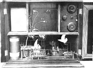
Rear view of the Retronic. The loop is moounted on the hinged door at the right.
Looking at the circuit, and reading the above description, reminds me of Hugo Gernsbach's "April Fool" articles which appeared in the April issues of his magazines during the thirties. Could this circuit really work? Some enterprising club member might give it a try! BMcC