The Engineering Behind the
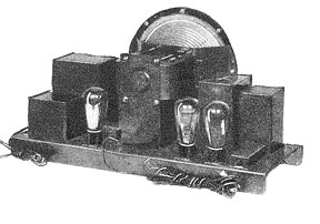
RCA Radiola Superheterodyne
By W.L. Carlson, R.S. Holmes, and N.E Wunderlich
The designers of this receiver

The following material has been reproduced from the November 1930 issue of Radio News. In 1930 RCA had released its patents on the Superheterodyne to its licensees, opening the market to greatly improved radio receivers. This RCA model was "state of the art" in 1930. It is also interesting to read the understanding of "high fidelity" described here.


>In order to give the excellent reception to which the present day broadcast listener is entitled, a receiver must give much better performance than would have been considered satisfactory a few years ago. It must be able to bring in the distant stations without interference from powerful local stations, and at the same time give high quality reproduction of programs coming from nearby stations.

The superheterodyne circuit is particularly adapted to meet these difficult requirements. Instead of relying on selecting and amplifying the signal at the incoming broadcast frequency, by means of circuits which must be adjusted to that frequency, the superheterodyne changes the broadcast frequency to a lower, fixed frequency where it can be amplified and unwanted frequencies eliminated much more efficiently. This fixed frequency is usually called the intermediate frequency.


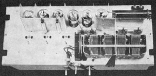
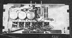
Top view of the RCA receiver chassis

The ease of obtaining high amplification and selectivity in an intermediate frequency amplifier is chiefly due to the relatively low frequency used and to the fact that the characteristics of such an amplifier are independent of the broadcast frequency to which the set is tuned. In the 1930 RCA Radiola superheterodyne an intermediate frequency of 175 kilocycles has been chosen as the best compromise between amplification, stability, selectivity and undesired responses.

Roughly the selectivity of a receiver is determined by the number of selective circuits it has. Thus, ordinary radio-frequency receivers have three or four tuned circuits. The better ones have five. The 1930 RCA Radiola superheterodyne has nine selective circuits, three at radio frequency and six at intermediate frequency. The fidelity of a receiver is usually considered to be a function of the audio frequency system and the loudspeaker. This assumption is true in regard to the lower acoustic frequencies. but at higher acoustic frequencies the high frequency amplifiers, in which the intermediate frequency amplifiers are included, play a large part. Thus, if the intermediate frequency characteristic of the receiver is such that it will attenuate the higher frequency side bands of the broadcast signal, the high acoustic frequencies will be lacking in the reproduction.

For good fidelity of reproduction, therefore, the resonance charac-teristic of the receiver should be broad enough to prevent attenuation of the high-frequency side bands. This characteristic in the 1930 RCA superheterodyne is obtained by the use of coupled circuits.

PRE-SELECTION and the RADIO-FREQUENCY AMPLIFIER

In order to eliminate extra responses in a superheterodyne, pre-selection at the incoming broadcast frequency is required. In any type of receiver it is desirable to have some selectivity before the first tube in order to eliminate inter-ference, such as secondary modulation. It is also desirable in a super-heterodyne to have a relatively high signal level at the grid of the first detector (or frequency changer) tube.

Thus in the 1930 superheterodyne there are two tuned circuits ahead of the first tube. These two circuits are so coupled as to give high attenuation to frequencies outside the desired band.


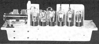
Rear view. The order of the tubes is (L to R) RF, Oscillator, mixer, two IF, and the detector. The power amplifier and supply was a separate assembly.

Following the radio-frequency tube is a capacity coupled radio-frequency transformer, which, with the tube, gives a uniform amplification of about thirty over the broadcast band.

OSCILLATOR and FIRST DETECTOR

The oscillator circuit is a conventional one for use with a three-element tube. It consists of a tuned grid circuit with a plate feed-back coil coupled to it. The grid of the tube is connected to the mid-tap of the tuned grid circuit to minimize change in oscillator frequency with tubes. The oscillator is self biased by means of a grid leak and blocking condenser.

The tuning elements of the oscillator circuit are so designed that the oscillator frequency is always approximately 175 k.c. higher than the frequency to which the radio-frequency system is tuned. The oscillator tuned circuit is coupled to the secondary of the radio-frequency transformer which is in the grid circuit of the first detector. The coupling is so arranged that the magnitude of the oscillator voltage on the first detector grid is correct for the most efficient rectification. In the case of the -24, used in this receiver, the peak value of oscillator voltage on the first detector grid is seven or eight volts.

HiFi? Note that at 5 kHz the response is down about 50%

 
INTERMEDIATE FREQUENCY AMPLIFIER

The function of the intermediate-frequency amplifier is to furnish the major portion of the amplification and selectivity of the receiver. It consists of three transformers and two amplifier tubes.

The first intermediate-frequency transformer is connected to the "local-distant" switch so that in the "local" position the selectivity is impaired slightly in order to prevent side-band attenuation. In the "distant" position the transformer is extremely sharp and offers greater attenuation to frequencies outside the desired band.

The transformer consists of a tuned primary connected in the plate circuit of the first detector and a tuned secondary connected in the grid circuit of the first intermediate amplifier tube. The secondary is partially shielded from the primary to loosen the coupling and improve the selectivity. The transformer is mounted in a copper can to keep the losses at a minimum, while at the same time shielding the transformer windings from other parts of the circuit. When the "local-distant" switch is thrown to the "local" position a resistor is thrown across the primary and another in series with the secondary to broaden the resonance of the transformer and reduce its amplification.

The second and third inter-mediate-frequency transformers are both alike, and consist of tuned primary and tuned secondary coupled tightly enough to give a broad top resonance characteristic with high attenuation to frequencies outside the desired band. These transformers are mounted in iron cans to shield them from other parts of the circuit and to add sufficient loss to prevent double peaks in the resonance characteristic. All three transformers have adjustable capacitors across both primary and secondary for accurate tuning.

AUDIO-FREQUENCY SYSTEM

Plate circuit rectification and a single stage of audio amplification are used in this receiver. This system eliminates the grid leak detector and two audio stages commonly used in the past. Plate circuit rectification eliminates the loss of high acoustic frequencies due to the time constant of the grid leak and condenser. The low audio gain causes a correspondingly low a.c. hum and decreases the tendency for microphonic howl.

The "Power Plant" described in the text. Tubes used are one 80 and two 45s.

The blasting and breaking up of the sound output, when tuning through a local station, is ordinarily due to overloading of the output tubes. This disturbance is reduced to a minimum in this receiver by designing the audio system so the detector overloads at about the same time as the audio tubes.

The two -45 tubes in push-pull are used in this receiver, thus providing a large output without distortion.

LOUD SPEAKER AND CABINET ACOUSTICS

The loud speaker used in this receiver is an improved electro-dynamic instrument especially designed to give excellent quality and high output without distortion.

Very great care has been taken in designing the cabinet for this receiver in order that the reproduction may be brilliant and faithful. Holes have been bored in the cabinet under the loud speaker to prevent cabinet resonance, and the dimensions of the cabinet are correct for the loud speaker used.


Overall response curve. Typical of the era.

"FUNCTION OF THE LOCAL-DISTANT" SWITCH

Switch The adjacent channel selectivity and the fidelity of broadcast receivers are so related that it is impossible to emphasize either of these characteristics without a corresponding sacrifice in the other. In general, the characteristic most desired in a receiver, when receiving distant stations, is good selectivity, so that the station may be satisfactorily received without interference from adjacent channels. In receiving local or powerful distant stations, where interference is usually less, the most desirable characteristic is good quality. The "local-distant" switch in this receiver is arranged to perform this function.

"Local" Position

At the "local" position the receiver is still very sensitive, but its selectivity is impaired slightly in order to get better tone quality. The receiver should normally be operated with this switch in the "local" position. In the "distant" position better sensitivity and selectivity are obtained, and throwing the switch to this position will give better volume on extremely weak signals and on all signals the frequency of which is but slightly different from powerful local stations. The difference in tone quality of the two positions of the switch, while noticeably better at the "local" position is still very good at either position. At times when the noise level is high, throwing the switch to the "distant position," even when receiving a local station, may give better results because of the greater selectivity of the receiver in this position.

VOLUME CONTROL

Volume control is accomplished b varying the control grid bias on the radio-frequency and first intermed-iate-frequency amplifier. This gives a balanced reduction in amplification at both radio and intermediate frequency when the volume control is reduced.

SHIELDING

The amount of shielding required in an ordinary receiver is determined, to a large extent, by its amplification or sensitivity. The purpose of the shielding is to eliminate feed-back which would cause instability or oscillation. In general, the higher the frequency to which an amplifier is resonant the more likely it is to be unstable. In a superheterodyne most of the amplification takes place at the low intermediate frequency, so that much less shielding is necessary than would be required at broadcast frequencies for the same sensitivity.


Underside of the receiver chassis

POWER SUPPLY

In the power supply a -80 rectifier tube is used. The filter system is especially designed to eliminate a.c. hum from the loud speaker. The loud speaker field is used as one of the inductive elements of the filter, so the total rectified current flows through its winding, providing a powerful magnetic field.

In order to eliminate resistance coupling through the power supply leads, the voltage divider resistors for the radio amplifier tubes are located on the chassis. All grid returns are grounded and most of the tubes are self-biased by their plate current flowing through resistors in their cathode circuits, further reducing any chance of coupling through common resistance.

DIAL INDICATOR

The dial indicator is of the projection type and is calibrated directly in kilocycles so that the receiver can be turned directly to a station once its frequency is known.

TESTING THE RECEIVER

In the construction of any receiver, the methods of testing the various components determine in a large measure the ultimate results to be obtained from that receiver. The Radiola superheterodyne is indicative of the truth of this statement.

Before assembly in the chassis, each component is tested in almost every conceivable way. Selectivity curves are run on radio-frequency transformers in such a manner that each transformer is individually tested before inserting it into its shield, and again after the shield is put on. The assembly is again tested after the coils are mounted on the chassis and wired up.

No laboratory could be more exact in their measurement work than the operators of these testing machines. The machines themselves are marvels of engineering ingenuity, and a description of them makes a separate story in itself.


Schematic of the RCA Radiola. The dotted lines indicate the two separate chassis.


Copyright © 2013 Southern California Antique Radio Society