By Arthur H. Lynch
Reproduced from the April 1927 issue of Radio News
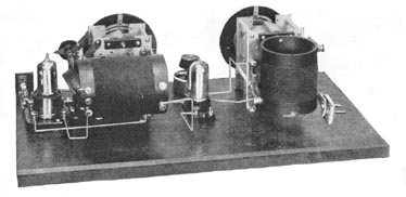
This is one of the earliest two-tube "bread-board" layouts of the now-famous Browning-Drake receiver. This was made several years ago (about 1924) but incorporates many of the mechanical design features introduced by W.A. Ready, one of the movers in bringing the B-D into thefavor it enjoys.
The Browning-Drake circuit, instead of following the path toward oblivion of many, other circuits which temporarily received national prom-inence through the radio press, has become more and more popular as time goes on, until now it is recognized as a standard by which the performance of others is judged.
In August, 1923, Glenn H. Browning and Fred H. Drake, engineering students at Harvard University, undertook, at the suggestion of the radio editor of the Christian Science Monitor, Mr. Volney D. Hurd, a theoretical and mathematical study of tuned-radio-frequency amplification with a view to determining the important factors to be considered in the design of such amplifiers. Messrs. Browning and Drake also developed, during the course of their work, formulae and equations which would enable them to determine and predict the theoretical gain, selectivity and tendency to oscillate of any radio-frequency amplifier. As a result of nearly a year of theoretical and laboratory work, a number of very important observations were made and thoroughly checked.
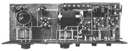
TOP: one of the four-tube receivers. Because of the simplicity of construction
this type was exceedingly popular until other forms of amplification became
available.
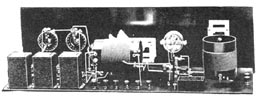
BOTTOM: An impedance-coupled five-tube set of a later period. This was designed
by Mr. Browning especially for the home constructor, and its mechanical as well as
its electrical merit made it a favorite. Even today (1927) it will not suffer by
comparison with many of the factory-assembled receivers.
ORIGINAL RESEARCHES
It was found that, by the proper design of a radio-frequency trans-former, practical results which very closely approximate the theoretical predictions may readily be obtained; the tendency of a radio-frequency amplifier to oscillate and the selectivity and sharpness of tuning may be predicted mathematically; and the most important constructional details to watch, in the design of a highly-efficient radio-frequency transformers, are: The use of low-loss condensers and low-resistance secondary coils, and the minimization of capacity coupling between the transformer primary and secondary. Such coupling induces a current in the secondary which is not in phase with that induced, as a result of the magnetic coupling, so that the resultant energy transfer is greatly reduced.
As a result of their researches, Browning and Drake were able to design the transformer, used in their original experimental set, shown below. Measurements made on this particular receiver showed a performance very close to that theoretically obtainable.
The secondary of the Browning-Drake transformer consists of 74 turns of No. 18 enameled copper wire, wound on a threaded 3-inch bakelite tube so that each turn is spaced from its neighbors by a distance equal to half the diameter of the wire. When tuned with a .00035-mf. low-loss condenser this transformer will cover the entire broadcast band.
Capacity coupling between the primary and secondary is reduced to a negligible quantity by using, for the primary, very fine wire wound in a narrow slot at the low-potential or filament end of the secondary. For this purpose, 24 turns of No. 30 double silk-covered wire should be used. The rather high radio-frequency resistance of such a winding is not at all detrimental, as the primary is connected in the plate circuit of a tube having a plate impedance of around 20,000 ohms. A few ohms more or less in series with 20,000 are quite negligible. The use of larger wire to reduce the primary resistance would greatly increase the capacity coupling between the primary and secondary, and thus really decrease the overall efficiency to a marked degree.
In developing the transformer without regeneration, the equations obtained indicated that with a tickler feed-back, or regeneration device, in the plate circuit of the detector tube and properly coupled to the transformer secondary, the signal strength could be increased between three and four times. Practical experiments soon confirmed this prediction.
Incidentally the addition of regeneration not only materially increased the distance-getting ability of the receiver, due to increased radio-frequency amplification or "gain," but also materially increased the selectivity and facilitated cutting through the local stations. The tickler coil consists of 20 turns of No. 26 wire on a bakelite tube 2-1/2 inches in diameter.
IMPROVEMENTS IN CIRCUIT
Browning and Drake, in their work, used the 199-type tube as a radio-frequency amplifier. This tube was selected in preference to others because of the ease with which circuits employing it could be neutralized or balanced, and also because of its economical consump-tion of filament power. The short useful life of the 199 was not at that time fully realized.
Knowing the advantage to be gained in volume and reliability by the replacement of the 199 with a standard five-volt tube, several other engineers have worked on different types of neutralizing devices that could be applied to the B-D circuit so as to enable the use of the 201A-type tube as a radio-frequency amplifier. At last such a device has been perfected by John F. Rider and Arthur Moss. The "Phasatrol," as the new neutralizer is called, operates on a principle different from that of any of the other systems. As its name indicates, its function is to change the phase of the R.F. current in the plate circuit of the radio-frequency amplifier tube.
As the plate of the R.F. tube works into an inductive reactance (the primary of the R.F. transformer) the phase of, the R.F. current in this circuit may be altered by the addition of a capacity in series with the trans-former primary. As the D.C. component of the plate current will not pass through a condenser, energy must be supplied to the plate of the tube through a suitable resistor. The "Phasatrol" consists of a fixed condenser of the proper size mounted in a compact unit with a variable high resistance, which may readily be adjusted to meet the requirements of any set. By altering the phase of the R.F. plate current of the R.F. amplifier tube, oscillations due to plate-circuit energy getting back to the grid circuit and re-enforcing the grid voltage will not occur; as the fed-back energy will not have such phase relations with the grid voltage as to cause oscillation.

The Phasatrol
The introduction of the Phasatrol compensating device in the Browning-Drake circuit permits the use of a 5-volt R.F. tube. (No neutralization is shown. Editor)
Mechanically the "Phasatrol," which is shown above, may be "one-hole mounted" under a sub-panel with just its adjustment screw exposed, or else may be mounted on a baseboard with the two screws provided for the purpose. The case is of molded bakelite.
With the "Phasatrol" used in place of the conventional system of neutralization originally employed by Browning and Drake, no difficulty is encountered in replacing the 199 R.F. amplifier tube, with one of the 201A type. Not only is the reliability and stability of the set greatly increased by this change, but also its sensitivity and volume. But even better results are obtained by the use of a new radio-frequency amplifier tube, known as "Type K," which is very easy to neutralize and gives a much greater gain than ordinary tubes.
AUDIO AMPLIFICATION
The fundamental Browning-Drake circuit comprises only the radio-frequency amplifier and regenerative detector, using the special B-D coils. In fact, the original models, such as shown on the previous page, were merely two-tube affairs employing no audio amplification. Naturally, different writers in describing the Browning-Drake receiver in the past preferred, and thus described, different forms of audio amplification. The commercial receiver employing the B-D circuit designed by Mr. Browning employed, at the suggestion of the writer, three stages of resistance-coupled amplification.
LEFT: The standard Browning-Drake circuit. RIGHT: A two-stage transformer-coupled A.F. amplifier with an output filter.
Schematic of a three-stage impedance-coupled audio frequency amplifier. Hi-mu tubes are used in the first two stages and a power tube in the output stage.
TOP: A three-stage resistance-coupled audio amplifier employing a grid impedance in the output stage to eliminate grid blocking. BOTTOM: An impedance-coupled three-stage audio amplifier using gred-circuit resistors.
During the past year great strides have been made toward the perfection of audio amplification. Transformer engineers, particularly George C. Crom, Jr., have developed transformers which give truly remarkable results; almost equal in fact, to the well-nigh perfect amplification obtainable with the modern resistance-coupled amplifiers.
RESISTANCE COUPLING AT ITS BEST
Resistance-coupled amplification, while long recognized for the excellent quality it was capable of delivering, had many drawbacks which have only recently been completely eliminated.
First, there was the difficulty in obtaining suitable resistors which would be silent in operation and remain permanent in value. Unfortunately, the metallized filament resistor could not be used as the input resistor when a special detector tube was employed. Attempts were made to substitute a transformer or an impedance for the input resistor, but such substitutions were always made at a slight sacrifice in quality. For the best of quality the load impedance must be higher than the tube-plate impedance; in the case of one of the new detector tubes, in which the plate impedance is unusually high, the only commercially practical way of obtaining an A.F. input device of sufficiently high impedance at the low frequencies so that it would not "lose" some of the low notes is to use a 100,000-ohm coupling resistor, capable of carrying six milliamperes continuously without noise or depreciation.
To construct a transformer which would have sufficient primary inductance and low enough secondary distributed capacity to meet these requirements, would he a most difficult engineering and economic under-taking. The right kind of resistance, which has long been recognized to be of the wire-wound variety, is the least expensive and most desirable solution. To wind such resistors commercially, however, is quite an undertaking; and it is only after many months of work that a practical process has been developed for winding the many thousands of turns of very fine wire, without breakage, into compact units of such high resistance.
Another objection to resistance-coupled amplification in the past was its lack of volume. This difficulty has been entirely overcome by the use of high-mu tubes, especially developed for the purpose.
Still another difficulty was the high voltage, so essential for the best of results with a resistance-coupled amplifier. The development of the "B" power unit has solved the high-voltage question, "
MOTOR BOATING
" As a result of the use of "B" units with resistance-coupled amplifiers, a new difficulty was encountered in some cases: a tendency for the amplifier to "motor-boat" or oscillate at an audio frequency, causing a noise similar to the "put-put" of a single-cylinder motor to come from the loud speaker. This difficulty has been completely overcome by James Millen in his audio system, by the use of a grid impedance for changing the phase of the grid circuit of the last or power audio tube. In the case of high-quality transformer-coupled amplifiers, the use of partially run-down "B" batteries or a power unit may result in the amplifier sounding "tinny." The cure for such trouble is to use audio-frequency chokes and large bypass condensers in the plate leads; especially the detector-tube plate head, as shown in the Phasatrol schematic.
Finally, but perhaps most important, came the placing on the market of really good loud speakers, which has served as an incentive to audio engineers to design companion amplifiers. One form of amplification which has attracted a great deal of attention of late is the dual-impedance amplifier. Such an amplifier is similar to an impedance-coupled amplifier, except for the fact that impedances are used in place of the grid resistors, as well as in the plate circuits.
THE POWER AMPLIFIER
During the past few months, as a result of the work done by James Millen and the writer, there is a growing tendency toward the use of separate audio amplifiers of the lamp-socket-operated variety. Thus, in the case of the Browning-Drake receiver, a two-tube set, without audio amplification, can be used with a separate amplifier unit. Regardless of the form of coupling used in an audio-frequency amplifier, good quality cannot be secured without the use of a power tube employing the proper plate and grid voltages. There are available for use in a receiver suited to the home two general types of power tubes—the 112 and the 171 types. The 171 is by far the better tube to use, as it is capable of delivering many times more undistorted power to the loud speaker than the 112. It must, however, be used with a socket-power unit, as it consumes far more "B" current (20 milliamperes at 180 volts, with proper "C" voltage) than is economically obtainable from "B" batteries. Where the use of batteries is essential, then the semi-power 112 tube should be used and the volume of the received signal kept down to prevent distortion due to overloading. The 112 is fairly economical of "B" power.
OUTPUT DEVICES
When using a power tube in an A.F. amplifier it is essential, for the best of quality and as a protection against damage to the loud speaker, to use an output device. There are two general types, the impedance-capacity units, known as tone filters, and the transformers. The tone-filter arrangement is more generally employed in connection with power amplifiers, because it is so designed that it eliminates A.F. current coupling between the plate circuit of the power tube and those of the other tubes. Although the phase of the A.C. in the plate circuit of the last tube, with respect to that in the other plate circuits, is generally of such an angle as not to cause trouble, it is well worth while to eliminate this possible cause of "motor-boating" and the choke coil-condenser method does this very effectively.
In a choke-coil condenser output device, the condenser should be of high capacity— 3- to 5-mf.--and the choke coil of high inductance, at least 30 henrys. As the direct current cannot pass through a condenser, the direct plate current is forced to flow through the choke coil in order to complete the D.C. circuit. The A.C., or the fluctuating component that actuates the loud-speaker mechanism, on the other hand, will readily pass through a large condenser, but not so readily through an inductance.
As the purpose of the capacity-inductance output device is to separate the plate current of the last or power audio amplifier into its two components, and to make each of these components go through separate circuits, it is essential, to obtain the best of quality, that the separation be complete. Thus, to prevent loss of the low notes, the inductance of the choke coil must be sufficiently high to prevent any appreciable amount of low-frequency audio current from passing through the choke coil rather than through the condenser and speaker. However, the D.C. resistance should be kept low to prevent a drop in the effective plate voltage on the power tube: A very great drop in this voltage is found when an ordinary loud speaker is connected directly in the plate circuit of this tube and is the direct cause of much distortion in ordinary receivers. The instructions accompanying the 112-type tube, for instance, call for a negative bias of 9 volts when 135 volts is used on the plate. Placing the speaker in this circuit cuts the 135 volts down very considerably and to maintain the proper bias the 9-volt tap should be reduced to about 7.5. The choke-condenser system rectifies this trouble.
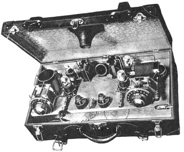
A suitcase receiver made in an early day with standard parts which were on the market at that time. Romm for the batteries is found under the base which is on hinges.
MECHANICAL IMPROVEMENTS
While such improvements, from an electrical point of view, are being made to the Browning-Drake system, it is only natural to expect improvements and refinements of equal importance along a mechanical line. Perhaps one of the most noticeable has been made in dials; we now have the variable-ratio vernier dial with an illuminated scale and place for recording the station call letters. The variable vernier permits of a rapid motion when tuning in local stations or in going from a station at one extreme of the broadcast wave band to one located at the other. The illumination is of the indirect variety, now in such vogue for automobile instrument boards. Then, too, the condensers have been mechanically changed so that they are more compact, and have lower electrical losses, lower minimum capacity, smoother action and a variety of plate shapes for different requirements. Perhaps the new plate shape, which gives results just halfway between straight-line-frequency and straight-line-wavelength, will be the most popular.